![]()
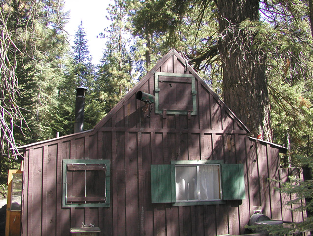
The Mineral King webcams are semi-autonomous imaging systems located at the Faculty Flat area of the Mineral King Valley and East Mineral King in Sequoia National Park. At approximately 36ş 27' N latitude and 118ş 37' W longitude, the altitude of the Faculty Flat webcam is 7,440 feet and the East Mineral King webcam is at 7,830 feet. Both webcam systems are self-contained and obtain power from solar panels. Although capable of true autonomous operation without the need for human intervention at all, the systems are capable of being operated and reconfigured from virtually any remote location in the world. There is no access to the Mineral King Valley from first snow until about May of each year so the systems' autonomy is critical to its continued viability.
The overall webcam project was first demonstrated during the 2005-2006 season with a single camera at Faculty Flat. In late-Summer of 2006 an additional webcam was installed at Potato Patch Ridge in East Mineral King. The addition of the EMK webcam affords a landscape view that is perhaps more familiar to Mineral King visitors.
The systems can be logically partitioned into six assemblies. The operation of these assemblies is routinely controlled and coordinated by software running on a server hundreds of miles away. The six major assemblies are identified and described in some detail below:
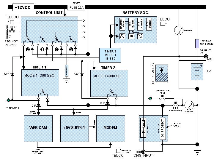
SCHEMATIC/BLOCK DIAGRAM OF WEBCAM SYSTEM
The Netcam and Server Subsystem is the heart of the webcam. The camera at Faculty is a standard Stardot webcam with a fixed lens having 33ş field-of-view. At East Mineral King the camera is a Stardot MP megapixel unit capable of true-color 1.3 megapixel images using a Sony 1/2 inch CCD sensor and a motorized zoom lens with a variable field-of-view from 8ş to 45ş. The cameras contain firmware in both EEPROM and Flash memory that can be altered remotely by the webmaster. The operating system of the webcam/server is embedded Linux. At the current time the webcams are configured to produce 640x480 full-color images using JPEG compression. Each camera is housed in a weather-proof enclosure and designed to operate to -40şC which is colder than ever recorded in the Mineral King Valley. Because solar-electrical power is so precious at Mineral King the cameras normally sit unpowered and await instructions from the control subsystem to activate a picture or configuration session. Watchdog timer assemblies within the control subsystem prevent the camera from staying powered indefinitely should a loss of communications occur.
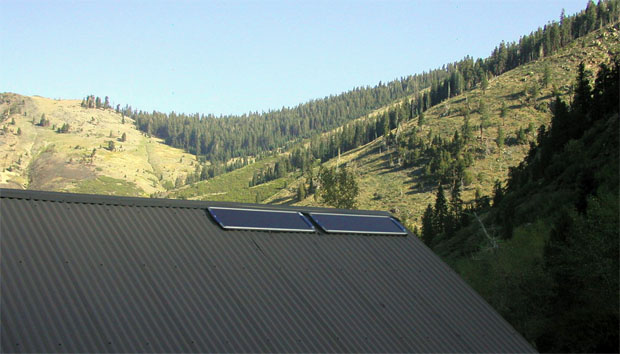
The Power Subsystem encompasses three main elements: solar panels, batteries and battery state-of-charge indicator. The solar panels are the sole source of energy from which the entire system operates. The panels are made by ICP Solar Technologies and are designed for use under extreme environmental conditions. There are three 5-watt panels at Faculty Flat that are spatially separated to provide power with changing shadows during the day. At Potato Patch Ridge there are two 18-watt solar panels with a clear view of the sun for more than 5 hours each day.
Because of the great variance of the sun's elevation angle during the year, and the greatly irregular elevation mask in the Mineral King valley, the panels are pointed to optimize solar input throughout the day and year. The panels are diode isolated from each other to prevent a system failure should one panel short or otherwise malfunction. Energy is stored in sealed lead-acid secondary cells with a total capacity of 79,000 mA*H at Faculty Flat and 158,000 mA*H at East Mineral King. The entire system operates at a nominal 12.6 volts. There is no high voltage anywhere in the system. The system consumes about 315 mA*H each 24 hours plus an approximately 100 mA*H for each picture session.
The state-of-charge (SOC) of the batteries can be determined from a custom-designed SOC indicator that provides audible telemetry when queried from a remote location. The SOC indicator can also provide insight into when, and how much, charging is taking place since the battery voltage rises when being charged. The SOC indicator is usually checked at least once each day, usually after sundown, to determine if the energy utilization and battery state is within the projected power budget. The control electronics also contains a controller circuit to prevent severe battery overcharging should that occur. Battery conditioning can be accomplished manually by applying a load resistor load via command from the control unit. This load, along with the current drawn by its control relay can be used to set the battery SOC to any value desired. This feature is especially useful during summer months when excess solar power is available.
|
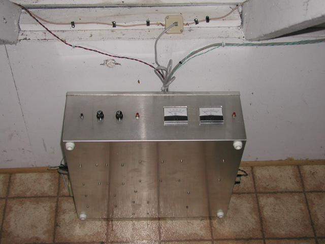
The Control Subsystem is a custom-made set of electronics that allows management of system operations and access to all system functions including the reprogrammable features of the webcam/server itself. It is the only element of the system that must reside inside a structure and protected from weather elements. |
||||
| The control subsystem contains electronic circuitry that includes four microcontrollers. One microcontroller constantly monitors the telco line to await an incoming call for control. All other electronics in the control unit are normally powered off until activated by incoming control signals that consist of standard DTMF tones sent from any remote location. Access to the control unit in the control subsystem is protected by password as well as tamper detectors to prevent unwanted intrusions into the system. Pass-through communications to the webcam has an additional firewall with a separate userid and password. | ||||
 |
||||
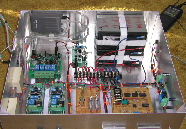
The control subsystem as shown above is in its final installed configuration at Faculty Flat in the attic of a cabin (that is now shuttered and dark and will remain that way until May of 2008). In the picture below the control subsystem is shown opened and horizontal. The original batteries (in the upper-right corner) have been replaced with a larger absorbed-glass-mat battery external to the unit. The modem is in the upper-left corner. There are three interfaces to the telco line: the modem, state-of-charge telemetry circuit, and the control unit. All circuits are fused and there is some block redundancy to provide for enhanced reliability during periods when physical access is impossible. Watchdog timers are used for all functions where excessive power drain could occur if communications was lost. All settable parameters of the control subsystem are stored in EEPROM to prevent against power loss (dead batteries for instance) and all telephone interfaces are protected by a varistor to guard against voltage transients that occasionally occur on telephone lines. The entire control subsystem has been environmentally tested to -20şC to assure its capability to operate through the cold temperatures prevailing during winter at Mineral King.
The Communications Susbystem is fairly straightforward and will be described only superficially here. The primary communications interface is with the control unit that is connected to an ordinary dial-up POTS (Plain Old Telephone Service) line. Ordinary DTMF tones are used for control and 1 KHz audio is utilized for the state-of-charge telemetry.
Once the signals enter the telco side of the interface they travel about one mile underground to a microwave station where they are radiated outside the National Park to Case Mountain in the San Joaquin Valley. From there they re-enter POTS circuits and make connection to the Internet. Once the Internet connection is made, File Transfer Protocol (FTP) is used to send the images to a web server in Colorado where they are available to anyone having a web browser client on the Internet. Along with the images is sent technical info about the camera and its current IP address for the picture session (DHCP is utilized so the IP address is not static from session-to-session). Using the IP address information allows the webmaster to access the camera/server and make any exposure, processing, and other adjustments that are necessary to keep the system working properly. The camera/server has a secondary firewall with user-ID and password interface separate from that of the control unit.
The entire webcam system is monitored 24/7 by a remote computer residing in Southern California. By using operating scripts on the remote computer the system can perform completely autonomously with no human intervention at all. However, operators can intervene and initiate additional operational activities at anytime desired simply by calling it from a cell phone. Management of files on the FTP server is also automated through scripts and no maintenance of that facility is needed except when changing web page design and/or adding additional content. An automated custom-written HTML editor is utilized to perform minor updates to the primary web page contents. This webcam system has been operating continuously since September 12, 2005.
The Mechanical Support and Cabling Subsystem is perhaps the most mundane but never-the-less important element of the overall system. It consists of the camera housing that is designed to take weather extremes; camera housing mounting bracket; all wiring both exterior and interior to the structure, wiring within the control unit subsystem assembly, and solar panel mounts and articulation hardware. All interfaces with the control unit are made via standard connectors. Connections to the camera/server and outside solar panels are made via special connectors either supplied by the manufacturer of those items or custom made. All exterior connectors have been sealed with silicone-acrylic adhesive for water protection. Exterior wiring is routed through plastic conduit to prevent degradation due to ultraviolet from the sun or gnawing by rodents.
|
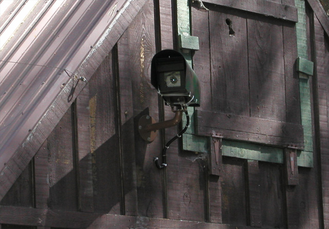
Although the camera/server external enclosure is designed to take severe weather there is a concern that snow buildup on the flat top of the enclosure could present a problem. For that reason, an additional "roof" was attached to the enclosure that is rounded on top and has air space underneath to facilitate warming. The rounded "roof" was simply fabricated by purchasing a plastic rural mailbox, much like you'd see by a home on a country road, and sawing it to fit securely over the camera housing. See pictures of the camera/server at the beginning of this article. |
|||
 |
|||
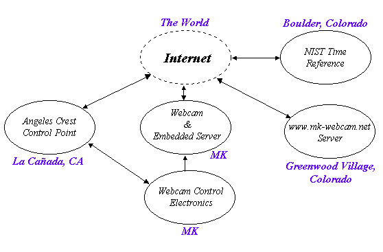
The Remote Data Subsystem consists of the hardware and software that maintain control over the operation of the entire system. The remote data subsystem is distributed over a distance of hundreds of miles in Southern California and in Colorado. The primary control of the entire webcam system is routinely done by a computer that runs 24 hours/day on Angeles Crest Highway (Calif. Hwy #2) in La Cańada, California. This location is named the "Angeles Crest Control Point" in the diagram below. The control point communicates with the Mineral King webcam control electronics via common telephone circuits. The MK control electronics then control power to the webcam itself. The webcam contains an embedded server that can communicate anywhere on the internet via modem. Once the webcam is connected to the internet by command from the control electronics it can then communicate directly (via internet) to the Angeles Crest Control Point for configuration and exposure settings. The webcam server also communicates (via internet) with the NIST in Boulder, Colorado, to get date and time. It then sends images and engineering information to a web server in Greenwood Village, Colorado (near Denver). When the web page is viewed by people surfing the web, they are seeing the image data and HTML stored on the server in Greenwood Village. The rest of the remote data system is invisible to web surfers. The web page is updated every 30 minutes by the Angeles Crest Control Point using FTP to send the new page to the Greenwood Village server.
How are temperature and snow depth measurements made? The camera/server itself contains an accurate temperature sensor intended to monitor the electronics temperature within the camera assembly. Since the camera/server sits unpowered the vast portion of the time that sensor stabilizes at the ambient outside air temperature where it resides until a picture session is initiated when it then begins to rise rapidly. Through careful calibration the camera sensor has been characterized versus the time since camera power-on and can be extrapolated back to the pre-powered value that should be very close to the air ambient temperature. An exception to this is for summer afternoon temperature measurements (after around 12:30 PM) when the sun is directly on the side of the camera housing. From then until sundown the initial temperature of the sensor is not representative of the ambient air. During that interval the air temperature is determined by obtaining data from nearby calibrated sources at Giant Forest, Three Rivers, Pumpkin Hollow, and other backup sensors. Those data are then adjusted for the atmospheric lapse rate to get the equivalent expected value at the 7,440 foot elevation of the camera. For more info about weather measurements displayed on the web site see "MK Website Weather FAQ" in the Special Features Menu.
Snow depth is determined in a much simpler manner. In each image you'll see a pole with alternating black and fluorescent orange markings. The pole is ten feet tall with the top marking being fluorescent orange. By simply counting down from the top, any observer should be able to determine the snow depth at the location of the pole. The pole itself it made from 2-inch diameter ABS pipe and is installed over a steel fence post driven deeply into the ground so it should remain stable throughout the winter. The site of the poles are mostly clear of large trees and the visible snow depth should be representative of the surrounding general area. Since the pole does receive afternoon light from the south the snow near the pole will be among the first to melt in springtime and should provide a good indication of the progression of road conditions as the area once again thaws from winter. Recognizing the resolution of the images from this system, snow depth can probably only be determined to about one inch.